 Code
CodeBattery Alarm Howto
Am I the only one who has done an "emergency" landing when the batteries went flat? No, I didn't think so! Here I will show you how to add a low battery alarm to your ArduPirate copter.
Parts you will need:
 Very loud piezo buzzer capable of running from 5v with a current of less than 40mA.
- A 1/4w resistor,
How it works:
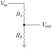
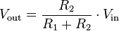
On the oil pan there is a section that has a number of analogue inputs that can measure voltage. But there is a complication with this: the microcontroller will measure the voltage assuming that it is somewhere between 5v and 0v, but that is not helpful when we are trying to measure a battery pack that is well over 5v! So what we need is something to scale the voltage down to a maximum of 5v. In electronics we call this a Voltage Divider. Thankfully for us the designers of the oil pan have included voltage dividers on the analogue inputs so all we need to do is calculate what resistors are needed.
You don't need to understand how all this actually works, I include it just for the people who would like to know.
On the oilpan R1 is already installed on the circuit board and has a value of 10K ohms (10,000) and R2 is empty. We now need to calculate the value of R2.
I'm using a 4 cell battery which has a fully charged voltage of 16.8v, this is Vin. Vout is 5v, and R1 is 10,000 ohms. Put those numbers into the equation and solve for R2, and you should get R2 = 4237 ohms. Now we have another complication - where do you buy a 4237 ohm resistor?? You don't. The nearest available values are 3.9k or 4.3k. If we use the 4.3k resistor we get an output voltage of 5.05v which is slightly above the maximum of 5v. Although it would work ok it's best not to because there is a small risk that we might eventually blow the input, especially if the input goes above 16.8v because of noise from the motors or something like that. If we use the 3.9k resistor we get an output voltage of 4.71v, which is much better and gives us a bit of headroom to spare. With a 10 bit analogue to digital converter this gives us a resolution of 4.71v / 2^10 = 4.6 mV/bit which is more than enough for our purpose.
(As a side note for the more adventurous, voltage dividers are not quite linear so the resolution will decrease (more voltage per bit) as the battery goes flat. As a homework exercise try graphing the output from the voltage divider in excel :)
Shut up already and tell me...